Mfr Part # A000066
ARDUINO UNO R3 ATMEGA328P BOARD
Arduino
License: GNU Lesser General Public License Microcontrollers Arduino ESP32
If you require more pins for your project to connect more buttons, sensors, or LEDs, GPIO expanders can help. Essentially, these expanders offer additional GPIOs when your board doesn't provide enough pins.
In this tutorial, we will learn how to use the PCF8574 I2C GPIO Expander with Arduino UNO or ESP32
Watch the video!
Learn more about Visuino: What is Visuino
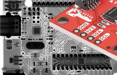
Arduino UNO or ESP32 (Or any other Board)
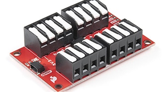
PCF8574 I2C GPIO Expander
To do the test experiment:
2x 1k ohm resistor
LED
Jumper wires
Breadboard
Visuino program: Download Visuino


Connecting LED:
Connect PCF8574 pin [0] to a 1K ohm resistor on the breadboard
Connect the other side of the resistor to the LED pin [positive +]
Connect the LED pin [negative -] to the breadboard negative pin [Black line]
Connecting Button:
Connect PCF8574 pin [1] to the button on the breadboard and to the resistor.
Connect the other side of the resistor to the breadboard pin [GND]
Connect the other pin of the button to the breadboard positive pin [5V]
Connect Arduino pin [5V] to breadboard positive pin [Red line]
Connect Arduino pin [GND] to breadboard negative pin [Black line]
Connecting PCF8574:
Connect PCF8574 pin [VCC] to breadboard positive pin [Red line]
Connect PCF8574 pin [GND] to breadboard positive pin [Black line]
Connect PCF8574 pin [SCL] to Arduino pin [SCL]
Connect PCF8574 pin [SDA] to Arduino pin [SDA]

Connecting LED:
Connect PCF8574 pin [0] to a 1K ohm resistor on the breadboard
Connect the other side of the resistor to the LED pin [positive +]
Connect the LED pin [negative -] to the breadboard negative pin [Black line]
Connecting Button:
Connect PCF8574 pin [1] to the button on the breadboard and to the resistor.
Connect the other side of the resistor to the breadboard pin [GND]
Connect the other pin of the button to the breadboard positive pin [5V]
Connect the ESP32 pin [5V] to the breadboard positive pin [Red line]
Connect the ESP32 pin [GND] to the breadboard negative pin [Black line]
Connecting PCF8574:
Connect PCF8574 pin [VCC] to breadboard positive pin [Red line]
Connect PCF8574 pin [GND] to breadboard positive pin [Black line]
Connect PCF8574 pin [SCL] to ESP32 GPIO pin [22]
Connect PCF8574 pin [SDA] to ESP32 GPIO pin [21]

Start Visuino as shown in the first picture. Click on the "Tools" button on the Arduino component (Picture 1) in Visuino. When the dialog appears, select "Arduino UNO" as shown in Picture 2 or "ESP32 Development Board" as shown in Picture 3


Add "PCF8574" component
Add "Pulse Generator" component
Select the "GPIO1" component, and in the properties window, set the I2C "Address". My module I2C address was 32. You can check the pins on the module and compare them to the table, as shown in Picture 4, or check Step 7.
Connect "PulseGenerator1" pin [Out] to "GPIO1" pin Channel 0 [In]
Connect "GPIO1" pin I2C [Out] to the Board pin I2C [In]
Upload the Project to the board; see the "Generate, Compile, and Upload the Arduino Code" Step on how to upload the project


Make sure that the module is connected to the board correctly (pins VCC, GND, SCL, SDA)
In Visuino, select the board and in the properties window expand "I2C Channels" > "I2C" > "Elements" and click on the 3 dots button
In the "Elements" window, drag "I2C Scan" to the Left side
Close the "Elements" window
Add "Start" component
Connect "Start1" component to the board pin [Scan]
Connect board pin [Address] to the board Serial pin 0 [In]
Upload the Project to the board; see the "Generate, Compile, and Upload the Arduino Code" Step on how to upload the project
Select the "Serial" tab, click the "Connect" button, and you should see the I2C Address of your module


Add "Debounce Button" component
Add "Toggle Flip Flop" component
Connect "GPIO1" pin Channel 2 [Out] to "Button1" pin [In]
Connect "Button1" pin [Out] to "TFlipFlop1" pin [Clock]
Connect "TFlipFlop1" pin [Out] to "GPIO1" pin Channel 1 [In]
Connect "GPIO1" pin I2C [Out] to the Board pin I2C [In]
Upload the Project to the board; see the "Generate, Compile, and Upload the Arduino Code" Step on how to upload the project


In Visuino, at the bottom, click on the "Build" tab, make sure the correct port is selected, then click on the "Compile/Build and Upload" button.
Note: If you are using an ESP32 dev board, then hold the "BOOT" when uploading the project

If you power the board in Experiment No. 1, the LED will blink, and in Experiment No.2, the LED will turn on or off if you press the button.
Congratulations! You have completed your project with Visuino. Also attached is the Visuino project that I created for this. You can download it here and open it in Visuino: https://www.visuino.eu