Send Temperature & Humidity SMS Every Minute to Your Phone - SIM900GSM &
2026-04-07 | By Ron Cutts
License: GNU Lesser General Public License Humidity Temperature Wifi Arduino ESP32
In this tutorial, you will learn how to send sms with Temperature and Humidity data using the SIM900 GSM Shield, DHT11 sensor and Visuino.
You can set your own timing. In this tutorial, we will use approx. 1 minute, but you can easily adjust the timing according to your needs,
Watch the Video!
Also check out these tutorials:
Make a Phone Call Using the SIM900 GSM Shield & Arduino - Visuino Tutorial
Send SMS Using SIM900 GSM Shield & Arduino - Visuino Tutorial
Learn more about Visuino: What is Visuino
What You Will Need
SIM900 GSM Shield
Arduino UNO
SIM card (You should disable the PIN request on the SIM card before using it with the GSM shield)
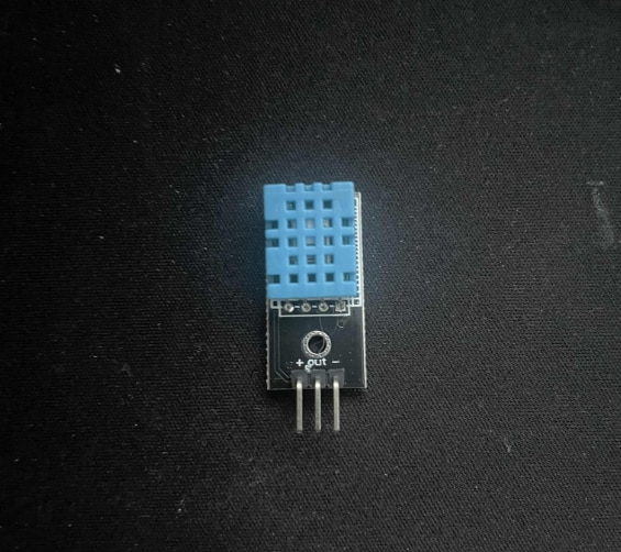
DHT11 Temperature & Humidity sensor
Jumper wires
5V power supply with enough amps for the shield
Visuino program: Download Visuino


The Circuit
Connect the SIM900 GSM Shield to the Arduino
Connect DHT11 pin [VCC] to Arduino pin [5V]
Connect DHT11 pin [GND] to Arduino pin [GND]
Connect DHT11 signal pin [S] to Arduino (shield) Digital pin [2]
Connect with the Jumpers on the shield pins D8(RX) & D7(TX) as you see it in the picture
Make sure that the antenna is connected to the shield
Connect the 5V Power Supply to the shield, and set the switch on the shield to the External Power (See the picture)
Once the Power is connected, hold the Power button for 2 seconds
Once the connection with the Network is established, the LED will blink every 3 seconds


Start Visuino, and Select the Arduino UNO Board Type
Start Visuino as shown in the first picture. Click on the "Tools" button on the Arduino component (Picture 1) in Visuino. When the dialog appears, select "Arduino UNO" as shown in Picture 2


In Visuino, Add Components
Add "Software Serial Port" component
Add "Text Value" component
Add "Sequence" component
Add "DHT11" component
Add "Char Value" component
Add "Text Multi-Source Merger" component
Add "Formatted Text" component


In Visuino Set Components
Double-click on the "TextValue1" and in the Elements window
Command to set GSM shield to text mode: drag "Set Value" to the left side and in the properties window set "Value" to AT+CMGF=1
Command to set Phone number (International Format): drag another "Set Value" to the left side and in the properties window set "Value" to AT+CMGS="+495XXXXXX"
Command to set Text Message: In the Elements window, drag another "Set Value" to the left side and in the properties window select "Value" and click on the pin Icon and select "String SinkPin"
Close the Elements window
Double click on the "FormattedText1" and in the "Elements" window drag 2X "Analog Element" to the left side, and for both set in the properties window "Precision" to 1
Close the Elements window
Select "FormattedText1" and in the properties window set "Text" to: TEMP: %0 HUM: %1
Select "CharValue1" and in the properties window set "Value" to #26
Select "Sequence1" and in the properties window set "Repeat" to: true
Double click on the "Sequence1" and in the "Elements" window, drag 4X "Period" to the left side
For the "Period1" in the properties window, set "Delay" to 5000
For the "Period1" in the properties window, set "Delay" to 15000
For the "Period1" in the properties window, set "Delay" to 20000
For the "Period1" in the properties window, set "Delay" to 25000
Close the Elements window


In Visuino Connect Components
Connect "Start1" pin [Out] to "Sequence1" pin [Start]
Connect "HumidityThermometer1" pin [Sensor] to Arduino Digital pin [2]
Connect "HumidityThermometer1" pin [Temperature] to to "FormattedText1" > "AnalogElement1" pin [In]
Connect "HumidityThermometer1" pin [Humidity] to to "FormattedText1" > "AnalogElement2" pin [In]
Connect "FormattedText1" pin [Out] to "TextValue1" > "Set Value3" pin [Value]
Connect "Sequence1" > "Period1" pin [Out] to "TextValue1" > "Set Value1" pin [Clock]
Connect "Sequence1" > "Period2" pin [Out] to "TextValue1" > "Set Value2" pin [Clock]
Connect "Sequence1" > "Period3" pin [Out] to "TextValue1" > "Set Value3" pin [Clock]
Connect "Sequence1" > "Period4" pin [Out] to "TCharValue1" pin [Clock]
Connect "TextValue1" pin [Out] to "TextMultiMerger1" pin [0]
Connect "CharValue1" pin [Out] to "TextMultiMerger1" pin [1]
Connect "TextMultiMerger1" pin [Out] to "SoftwareSerial1" pin [In]
Connect "SoftwareSerial1" pin [RX] to Arduino Digital pin [7]
Connect "SoftwareSerial1" pin [TX] to Arduino Digital pin [8]
Optional if you want to monitor response from the GSM shield: Connect "SoftwareSerial1" pin [Out] to Arduino Serial pin [In]


Generate, Compile, and Upload the Arduino Code
In Visuino, at the bottom, click on the "Build" Tab, make sure the correct port is selected, then click on the "Compile/Build and Upload" button.

Play
When you power the Shield, wait a bit for the connection with the network to be established. Once the connection is established, the LED on the shield will blink every 3s.
The "Start" component will automatically start the "Sequence" component, and the "Sequence" component will first set the GSM shield into Text mode, set the phone number, set the sms based on values from the DHT11 sensor, and send sms.
Congratulations! You have completed your GSM project with Visuino. Also attached is the Visuino project that I created for this Tutorial. You can download and open it in Visuino: https://www.visuino.eu