Mfr Part # ABS+175R1
ESUN ABS (1.75MM,1000G)RED
eSUN
License: See Original Project 3D Printing
Welcome to my journey of building a Voron Trident 300.
First things first: What is Voron Design? The goal of Voron Design is to enable everyone to build their own unique 3D printer, fine-tuned to their preferences and needs. There are two kinds of parts: Some are 3D printed by your own existing printer, 3D printing service, maker space, fab lab, or a member of the Voron community. The others are off-the-shelf parts you can buy in hardware stores or online from different sources like DigiKey. Everything is open source, which enables you to modify and customize your printer to match your needs. Further information is available on the Voron Design Website.
Why here? Even though the internet provides hundreds of video guides, and the Voron Design Team's manual is great, I wanted to document my journey, struggles, and solutions. I hope you’ll enjoy it as much as I enjoyed the build. Last, but not least, it is a thank you to the Voron Design Team for recommending DigiKey in their official sourcing guide: Voron Design Sourcing Guide.
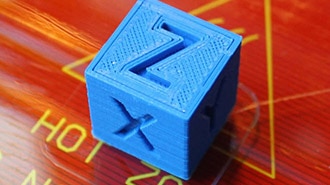
Figure 1: Voron 2.4 printer printing Voron Trident parts
Step 1: 3D Printed Parts
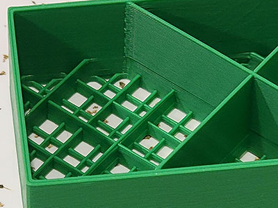
Printed parts I’m a lucky maker and have my own 3D printers so I can print my own parts. It is highly recommended to print the parts according to Voron Design specifications. This was tested by the Voron Design Team and the community. If you don’t own a 3D printer yet, you can use 3D printing services, maker spaces, or fab labs in your area. Where can I find the 3D models? Voron Trident STLs or use the Voron Design GitHub Repository. Please make sure to print the right parts and keep your modifications in mind. I used eSun ABS+.
Figure 2: Keeping track and sorting of all printed parts.
Step 2: Building the Frame
To build your frame, you can order standard 2020 aluminum extrusion, cut it, drill it, and add threads per Voron guides and manual.
Figure 3: All extrusions laid out.
However, I opted for convenience and ordered a pre-manufactured frame kit in a vibrant red color. While this step might seem straightforward, it's actually one of the most critical phases of the entire build. Ensuring that everything is precisely squared and tightly secured is essential. Neglecting this step could lead to complications later on, especially when attempting to troubleshoot issues arising from a misaligned frame.
After receiving the frame kit, I took the time to label the extrusions. These components can easily be confused, so clear labeling proved invaluable for streamlining the assembly process and minimizing errors.
Figure 4: Labeled extrusions
An indispensable ally during assembly is thread locker. I personally rely on Loctite 243 for this purpose.
Figure 5: Loctite I used
Figure 6: Assembled frame
Step 3: First Mistake and Linear Rails
Unfortunately, I forgot to add the bars to the extrusions in step 2, so I had to partially disassemble the frame and add the bars for the linear rails. This step marks my first modification. I opted for these bars instead of the T-nuts mentioned in the official manual because it is easier than aligning the T-nuts.
Figure 7: Mounting bar for linear rails
After rectifying this mistake, I double-checked to ensure everything was square before proceeding with A/B motor mount and the linear rails.
Figure 8: Applying brass heat-set inserts
Figure 9: Assembled A drive.
Figure 10: A and B drive mounted to the frame.
Figure 11: Extrusion added.
Figure 12: Back Z-rail support brackets.
I cleaned the rails to remove any oil residue and applied fresh grease to both the rails, and inside the carriage from the back. Since there isn't a convenient option to do this later, I completed this step now. Otherwise, the whole movement system has to be disassembled to reach the back of the rails.
For readers in North America, this cleaner is recommended, along with this type of grease. However, due to shipping restrictions (I’m located in Europe), I had to rely on my local hardware store.
Figure 13: Cleaning the rails.
I printed the linear rail guides twice to ensure perfect alignment.
Figure 14: Y-axis rails
With some time left today, I also installed the Z carrier and the motor mounts.
Figure 15: Z-rails, Z-carriers, and Z-motor mounts
Step 4: Motors and X-Axis
Similar to the process with the linear rails, I cleaned the lead screws on all three Z motors and attached them to the Z carriers. Next, I securely screwed the motors into place. Following this, I applied the same grease as used on the linear rails.
Figure 16: Z-motors mounted
Figure 17: Applying grease.
Please ensure to double-check the orientation and the T-nuts for mounting the printer's feet. There are two sizes of T-nuts used, and extracting them from the extrusions, if the wrong size is used, can be challenging.
Figure 18: M5 and M3 T-nuts
Figure 19: mounted feet.
The assembly of the X carriers was straightforward for me, having previously done the same on my Voron 2.4. Installing the linear rails proceeded as before. It's important not to fully tighten the screws for the X carrier, as specified in the manual. We need them to be loose to square the X-axis.
Figure 20: X and Y carrier parts
Figure 21: Mounting the X-rail
To facilitate the installation of the X-axis, I left the printer upside down. After adding the cable guide, I took my time to properly square the X-axis. Then, I fully tightened the screws in the X carriers.
Figure 22: squaring the gantry
Step 5: Setting Up the Belts and Preparing the Bed
This part can be quite intricate, and it's essential to ensure everything operates smoothly. I carefully inspected every corner and pathway to avoid any issues. It's crucial to prevent the belts from rubbing against anything, as this could damage them and affect print quality later.
Figure 23: Clamping down one side of the belts with the X-carrier
Figure 24: routing the belts carefully
Figure 25: Optimistic belt length calculation
Initially, I installed the inductive probe, but I plan to replace it with the tap mod after testing the printer thoroughly.
Figure 26: Omron probe installed with glass fiber insulation tape to protect probe from heat.
Moving on, I prepared the heat bed, which came with a preinstalled heater and thermal fuse. Before proceeding, I cleaned it with degreaser and isopropyl alcohol. Then, I applied the magnetic sticker provided with the build plate, making sure to eliminate any air bubbles between the heat bed and the adhesive.
Figure 27: Heat bed
Figure 28: Cleaning heat bed with IPA
Figure 29: Magnetic sheet attached
Lastly, I placed some weights on the back of the heat bed and will let it set for 24 hours.
Figure 30: Filament spools as weight
Step 6: Installing the Heat Bed
Figure 31: PE wire attached
To ensure safety, I installed the ground cable to the heat bed first. I wanted to make sure I didn’t miss this critical step. Next, I prepared the bed connections for the wires. In the picture above, you'll notice the standard version with only Wago splice connectors, which I might reserve for later use in the electronics bay. However, I opted for the other version, featuring a tiny PCB with soldered JST XH connectors, to ensure a secure thermistor connection.
Figure 32: Below heat bed distribution options
Following this, I readied the bedframe. It's essential to double-check the correct orientation and T-nuts to avoid the hassle of disassembling both the printed parts and the bed again.
Attaching the GE5C bearings to the printed parts was straightforward. With just six screws, everything was securely fastened and neatly in place. Afterward, I slightly loosened the screws to shake and wiggle the bed frame, ensuring everything settled into place, before tightening them again. Yes, contrary to the manual's recommendation, I even fully tightened the bed, as tomorrow I'll be turning the printer upside down for the electronics installation.
Figure 33: Heat bed frame mounts with bearings
Figure 34: Mount attached to the bed frame
Figure 35: Heat bed installed
Step 7: Preparing the Electronics
A black acrylic sheet is being used to protect the electronics. I've ensured that the wire covers are positioned correctly.
Figure 36: Black acrylic sheet attached
Figure 37: Checking wire cover for alignment
To secure the acrylic sheet in place, I've added zip tie clips. Departing from the manual, I've adjusted the layout of the DIN rails to accommodate cooling fans and the length of the display cable.
Figure 38: 3D printed zip tie clips to keep the acrylic sheet in place
Figure 39: Mounted DIN rails.
Next, I've installed heat sinks for the Raspberry Pi 4 and the stepper drivers. Additionally, I've mounted the DIN rail mounts and prepared the driver board. I've chosen the Big Tree Tech Octopus with matching drivers for easier configuration. Alternatively, you can use the TMC2209 Evaluation board, but programming adjustments are necessary. I've carefully set the jumpers to the correct configuration to prevent damage to the board or the drivers. The same attention to detail applies to the fan voltage adjustment.
Figure 40: Raspberry Pi with heat sinks
Figure 41: TMC2209 driver with heat sink
DIN rail mounts have also been attached to all boards, the power supply, and the Omron solid-state relay. This relay is the recommended choice per the Voron sourcing guide.
Figure 42: DIN rail mounts for the electronics
Figure 43: Attached DIN rail mount
Figure 44: Back of driver board with DIN rail mounts
Figure 45: Setting the jumpers
Figure 46: Installing TMC2209 driver boards
Figure 47: Raspberry Pi with DIN rail mount
Figure 48: Omron relay with DIN rail mount
Figure 49: Break out board for easier wiring the tool head
For distributing mains voltage, DIN rail terminal blocks and Wago splice connectors will be used. I highly recommend the Wago clamp DIN rail mount.
Figure 50: Relay, power supply, and terminal blocks installed to DIN rail
Electronics have been added to the skirts. I've incorporated a 4.3” touch display for the Raspberry Pi and connected it with the FFC cable to the display port. Additionally, I've installed 16mm diameter anti-vandal push buttons for 230V mains, as I am located in Europe. Consequently, I've opted for the Mean Well RSP-200-24 power supply. The black switch currently serves no function, but I may assign a use to it later. The power inlet has an integrated switch, which I won't use due to the presence of the switch in the front skirt (https://www.printables.com/model/490860).
Figure 51: Installing FFC cable to touch screen
Figure 52: Skirt parts with electronics
The final task for today was to mount all parts to the DIN rails and attach the prepared skirt parts.
Figure 53: Installed Boards, power supply, terminal blocks, relay, and 3 skirt parts
Step 8: Connecting the Cables
Motor connections and cables for the breakout board are fitted with JST XH connectors. I highly recommend labeling and marking all cables to maintain clarity and organization. From the breakout board to the tool head board, a 14-pos. Molex Microfit 3.0 connector with matching male connectors on the board is used for connectivity.
Figure 54: Mains and motor cables were the first to install
I've documented which sensor, switch, and fan are connected to each connector on the driver board, providing a reference for later configuration adjustments.
To ensure some degree of cable management, I've installed plastic clamps leftover from assembling my PC. Alternatively, a wide range of cable fasteners or zip tie mounts can be utilized. Comprehensive cable management will be undertaken once the wiring above the acrylic sheet is completed.
Figure 55: All cables installed
I've prepared the drag chain for the bed wiring and routed all cables from the heat bed to the electronics bay. During this process, I realized that the cutout was too close to the motor, necessitating adjustments without causing damage to the cables.
Figure 56: Drag chain preparation.
Figure 57: Installed Z drag chain
Step 9: Tool head Assembly
The assembly of the Stealthburner tool head is detailed in its respective manual found here: https://vorondesign.com/voron_stealthburner
Figure 58: Front cover of the Stealthburner with additional hex pattern (https://www.printables.com/model/225153 )
For this setup, I opted to use the E3D Voron Revo hotend as outlined in the manual. Notably, I've integrated the ERF Filament Cutter, providing precise filament cutting functionality and no need for a Filament tip-forming process with the ERCF V2 setup.
Figure 59: Tool head parts
The ERCF (Enraged Rabbit Carrot Feeder) is an open-source filament-changing system designed for Klipper-operated printers like mine.
To prepare for assembly, I customized the extruder motor, shortening its cable and terminating it with a JST XH 4-pin connector to fit neatly into the system.
Figure 60: Cutting the motor wires
The assembly process proved complex this time around, as I had to reference three manuals simultaneously. Due to the required modifications for the ERF cutting blade mount, I needed to adapt the acceleration sensor mount. This involved using longer M3x20 screws, an M3 nut, and two heat-set inserts as stand-offs, secured with thread locker to ensure stability for precise resonance measurements later on.
Figure 61: Filament cutter assembled
Figure 62: Acceleration sensor
However, a significant challenge arose when I discovered that the modified Clockwork 2 extruder with mounts for two micro switches was incompatible with the existing old tool head board I had on hand. It was quite frustrating since I’d prepared everything using this tool headboard and planned to have this step finished today.
Consequently, rather than proceeding with wiring the tool head, I had to order a new Stealthburner Tool head PCB. Once it arrives, I'll need to rewire the extruder motor connector before continuing with the assembly.
As a result, work on this phase is temporarily postponed until the new tool head PCB is delivered.
Step 10: Tool head Part 2
The eagerly awaited two-piece tool head board arrived, prompting me to carefully recrimp the connectors to accommodate JST PH connectors instead of JST XH. With everything prepared, I proceeded to mount the tool head according to the instructions in the Stealthburner manual and neatly connected all the cables. After determining the final cable lengths, I secured them with drag chains and ensured tidy placement within the electronics bay.
Figure 63: 2 pieces tool head PCB
Figure 64: Changing connectors and crimp contacts
Figure 65: Motor wired according to specification
Notably, the new tool head PCB features a different wiring setup compared to its predecessor. The connector originally designated for the chamber thermistor now serves an additional purpose: supplying 5V to the board for LEDs or other sensors. Placing the thermistor alongside the Z-axis drag chain, I was ready for the moment of truth—powering it on for the first time.
Figure 66: Assembled tool head
Figure 67: Zip ties for strain relief
Figure 68: Drag chains assembled
Figure 69: Modified NTC Thermistor 4316-104NT-4-R025H42G-ND for measuring chamber temperature
Figure 70: Thermistor mounted next to Z drag chain mount
A rush of satisfaction washed over me as I watched the LEDs illuminate, signaling that everything was functioning perfectly so far.
Figure 71: Electronics powered up for the first time
Part 2 of my Voron Trident 300 3D printer build will showcase the process of installing the firmware, calibrating the printer, and achieving the first print. Stay tuned for more updates.